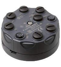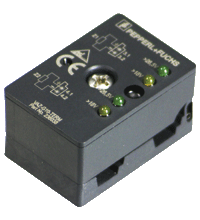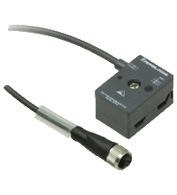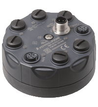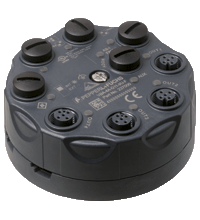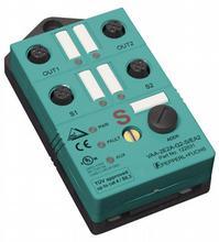
VAA-2E2A-G2-S/EA2
Артикул: 122531
AS-Interface safety module
11 886 Р
Производитель:
PEPPERL+FUCHS
Поделиться:
Производитель: PEPPERL+FUCHS
(!) Производство этого продукта прекращено, изделие имеет замену. Перейти к странице изделия-замены. VAA-2E2A-G12-SAJ/EA2L
Краткое описание: технические характеристики VAA-2E2A-G2-S/EA2
| Описание оборудования | ||
|---|---|---|
| G2 safety module 2 safety-related inputs and 2 conventional electronic outputs |
||
| General specifications | ||
|---|---|---|
| Slave type | Safety-Slave | |
| AS-Interface specification | V2.1 | |
| Required master specification | ≥ V2.1 | |
| UL File Number | E87056 | |
| Functional safety related parameters | ||
| Safety Integrity Level (SIL) | SIL 3 | |
| MTTFd | 200 a | |
| Indicators/operating means | ||
| LED FAULT | error display; LED red red: communication error or address is 0 red flashing: Output supply overload |
|
| LED PWR | AS-Interface voltage; LED green | |
| LED AUX | ext. auxiliary voltage UAUX ; LED green | |
| LED IN | switching state (input); 2 LED yellow | |
| LED OUT | Switching state (output); 2 LED yellow | |
| Electrical specifications | ||
| Auxiliary voltage (output) | 24 V DC ± 15 % PELV | |
| Rated operating voltage | 26.5 ... 31.6 V from AS-Interface | |
| Rated operating current | ≤ 70 mA | |
| Protection class | III | |
| Input | ||
| Number/Type | 2 safety-related inputs for mechanical contacts, cross-circuit monitored: 2 single-channel contacts: up to category 2 in accordance with EN 954-1 or 1, 2-channel contact: up to category 4 in accordance with EN 954-1 Cable length must not exceed 30 m per input. |
|
| Supply | from AS-Interface | |
| Voltage | 20 ... 30 V DC pulsed | |
| Current loading capacity | input current limited ≤ 15 mA, overload and short-circuit resistant |
|
| Output | ||
| Number/Type | 2 conventional electronic outputs, PNP | |
| Supply | from external auxiliary voltage UAUX | |
| Voltage | ≥ (UAUX - 0.5 V) | |
| Current | 1 A per output | |
| Compliance with standards and directives | ||
| Directive conformity | ||
| EMC Directive 2004/108/EC | EN 61326, EN 50295, EN 61496-1 | |
| Standard conformity | ||
| Electromagnetic compatibility | EN 61000-6-2, EN 61000-4-5 1 kV asymmetric, criterion B, EN 61000-6-4 | |
| Emitted interference | EN 61000-6-4:2001 | |
| Insulation coordination | EN 50178:1998 | |
| Functional safety | EN 954-1:1996 (up to category 4), BIA Final Draft "Proposal for a principle to the verification and certification of field busses for transmission of safety related signals" 28.05.2000, IEC 61508 up to SIL3 | |
| Degree of protection | EN 60529:2000 | |
| Fieldbus standard | EN 50295:1999, IEC 62026-2:2006 | |
| Electrical safety | EN 50178:1998 , IEC 60204-1:2007 | |
| Standards | NFPA 79:2002 | |
| Programming instructions | ||
| Profile | S-7.B | |
| IO code | 7 | |
| ID code | B | |
| ID1 code | F | |
| ID2 code | 0 | |
| Data bits (function via AS-Interface) | ||
| D0 | ||
| D1 | ||
| D2 | ||
| D3 | ||
| Parameter bits (programmable via AS-i) | function | |
| P0 | Logic operation: P0 = 1 (default settings): The outputs are controlled via AS-Interface. P0 = 0: The outputs are controlled via AS-Interface or the inputs. The corresponding output is activated on opening the contacts of an input. |
|
| P1 | not used | |
| P2 | not used | |
| P3 | not used | |
| Ambient conditions | ||
| Ambient temperature | -25 ... 55 °C (-13 ... 131 °F) | |
| Storage temperature | -25 ... 85 °C (-13 ... 185 °F) | |
| Shock and impact resistance | 15 g, 11 ms in 6 spatial directions 3 shocks 10 g, 16 ms in 6 spatial directions 1000 shocks |
|
| Vibration resistance | 0.75 mm 10 ... 57 Hz , 5 g 57 ... 150 Hz, 20 cycles | |
| Mechanical specifications | ||
| Degree of protection | IP67 | |
| Connection | Cable piercing method flat cable yellow/flat cable black inputs/outputs: M12 round connector |
|
| Material | ||
| Housing | PBT | |
| Mass | 100 g | |
| Mounting | Mounting plate | |
Оформить заказ на VAA-2E2A-G2-S/EA2 вы можете в компании compeq-pepperl отправив заявку по почте, а также по телефону или в офисе компании.
Вам может понравиться