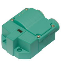
NCN3-F31K-N4-B13-S
Артикул: 281187
Inductive sensor
8 271 Р
Производитель:
PEPPERL+FUCHS
Поделиться:
Производитель: PEPPERL+FUCHS
Краткое описание: технические характеристики NCN3-F31K-N4-B13-S
| General specifications | ||
|---|---|---|
| Switching function | 2 x normally closed (NC) | |
| Output type | NAMUR | |
| Rated operating distance | 3 mm | |
| Installation | flush mountable | |
| Assured operating distance | 0 ... 2.4 mm | |
| Actual operating distance | 2.7 ... 3.3 mm typ. | |
| Actuating element | Stainless steel 1.4305 / AISI 303 8.5 mm x 8.5 mm x 0.5 mm |
|
| Reduction factor rAl | 0.5 | |
| Reduction factor rCu | 0.4 | |
| Reduction factor r304 | 1 | |
| Reduction factor rSt37 | 1.3 | |
| Reduction factor rBrass | 0.6 | |
| Output type | 2-wire | |
| Nominal ratings | ||
| Nominal voltage | 8 V | |
| Switching frequency | 0 ... 3 kHz | |
| Hysteresis | typ. 5 % | |
| Reverse polarity protection | reverse polarity protected | |
| Short-circuit protection | yes | |
| Suitable for 2:1 technology | yes , Reverse polarity protection diode not required | |
| Current consumption | ||
| Measuring plate not detected | ≥ 3 mA | |
| Measuring plate detected | ≤ 1 mA | |
| Time delay before availability | ≤ 1.1 ms | |
| Switching state indicator | LED, yellow | |
| Valve status indicator | LED, yellow | |
| Functional safety related parameters | ||
| Safety Integrity Level (SIL) | SIL 2 | |
| MTTFd | 1470 a | |
| Mission Time (TM) | 20 a | |
| Diagnostic Coverage (DC) | 0 % | |
| Valve circuit | ||
| Voltage | max. 32 V DC | |
| Current | max. 240 mA | |
| Short-circuit protection | no | |
| Reverse polarity protection | yes, with reversed output LED is out of function, therfore more power for solenoid valve | |
| Compliance with standards and directives | ||
| Standard conformity | ||
| NAMUR | EN 60947-5-6:2000 IEC 60947-5-6:1999 |
|
| Electromagnetic compatibility | NE 21:2007 | |
| Standards | EN 60947-5-2:2007 EN 60947-5-2/A1:2012 IEC 60947-5-2:2007 IEC 60947-5-2 AMD 1:2012 |
|
| Approvals and certificates | ||
| EAC conformity | TR CU 012/2011 | |
| CCC approval | CCC approval / marking not required for products rated ≤36 V | |
| Ambient conditions | ||
| Ambient temperature | -25 ... 100 °C (-13 ... 212 °F) | |
| Storage temperature | -40 ... 100 °C (-40 ... 212 °F) | |
| Mechanical specifications | ||
| Connection (system side) | Screw terminals, tightening torque min. 0.5 Nm Stripped length 7 mm |
|
| Core cross-section (system side) | rigid: 0.14 ... 2.5 mm2 flexible: 0.14 ... 1.5 mm2 flexible with core-end sleeve: 0.25 ... 1.5 mm2 |
|
| Connection (valve side) | like connection (system side) | |
| Core cross-section (valve side) | like core cross section (system side) | |
| Housing material | PBT | |
| Sensing face | PBT | |
| Degree of protection | IP67 | |
| Tightening torque, housing screws | 1 Nm | |
| Tightening torque, cable gland | M20 x 1.5 ; max. 7 Nm | |
| Note | LED switch-off | |
| Data for application in connection with hazardous areas | ||
| Equipment protection level | Ga , Gb , Gc (ic) , Mb | |
| Equipment protection level Ga | ||
| Type of protection | intrinsic safety | |
| CE marking | [*PD-Z02585A*] | |
| Certificates | ||
| Appropriate type | NCN3-F31K-N4... | |
| ATEX certificate | TÜV 99 ATEX 1479 X | |
| ATEX marking |  II 1G Ex ia IIC T6...T1 Ga II 1G Ex ia IIC T6...T1 Ga |
|
| Standards | EN 60079-0:2012+A11:2013 , EN 60079-11:2012 | |
| IECEx certificate | IECEx TUN 17.0021X | |
| IECEx marking | Ex ia IIC T6...T1 Ga | |
| Standards | IEC 60079-0:2011 , IEC 60079-11:2011 | |
| Effective internal capacitance | max. 100 nF The value is applicable for one sensor circuit. A cable length of 10 m is considered. |
|
| Effective internal inductance | max. 100 µH The value is applicable for one sensor circuit. A cable length of 10 m is considered. |
|
| Maximum permissible ambient temperature | Also observe the maximum permissible ambient temperature stated in the general technical data. Keep to the lower of the two values. |
|
| for ATEX | at Ui = 15 V , Ii = 25 mA , Pi = 34 mW , T6 : 55 °C (131 °F) T5 : 65 °C (149 °F) T4 : 95 °C (203 °F) T3 : 95 °C (203 °F) T2 : 95 °C (203 °F) T1 : 95 °C (203 °F) at Ui = 16 V , Ii = 25 mA , Pi = 64 mW , T6 : 55 °C (131 °F) T5 : 65 °C (149 °F) T4 : 95 °C (203 °F) T3 : 95 °C (203 °F) T2 : 95 °C (203 °F) T1 : 95 °C (203 °F) at Ui = 16 V , Ii = 52 mA , Pi = 169 mW , T6 : 45 °C (113 °F) T5 : 60 °C (140 °F) T4 : 85 °C (185 °F) T3 : 85 °C (185 °F) T2 : 85 °C (185 °F) T1 : 85 °C (185 °F) |
|
| for IECEx | at Ui = 15 V , Ii = 25 mA , Pi = 34 mW , T6 : 70 °C (158 °F) T5 : 85 °C (185 °F) T4 : 100 °C (212 °F) T3 : 100 °C (212 °F) T2 : 100 °C (212 °F) T1 : 100 °C (212 °F) at Ui = 15 V , Ii = 25 mA , Pi = 64 mW , T6 : 70 °C (158 °F) T5 : 85 °C (185 °F) T4 : 100 °C (212 °F) T3 : 100 °C (212 °F) T2 : 100 °C (212 °F) T1 : 100 °C (212 °F) at Ui = 15 V , Ii = 52 mA , Pi = 169 mW , T6 : 65 °C (149 °F) T5 : 80 °C (176 °F) T4 : 90 °C (194 °F) T3 : 90 °C (194 °F) T2 : 90 °C (194 °F) T1 : 90 °C (194 °F) |
|
| Maximum values of the valve circuit | The value applies to each valve circuit. A cable length of 10 m is considered. |
|
| Voltage | max. 32 V | |
| Current | max. 240 mA | |
| Internal capacitance | max. 10 nF | |
| Internal inductance | max. 20 µH | |
| Equipment protection level Gb | ||
| Type of protection | intrinsic safety | |
| CE marking | [*PD-Z02585A*] | |
| Certificates | ||
| Appropriate type | NCN3-F31K-N4... | |
| ATEX certificate | TÜV 99 ATEX 1479 X | |
| ATEX marking |  II 1G Ex ia IIC T6…T1 Ga II 1G Ex ia IIC T6…T1 Ga |
|
| Standards | EN 60079-0:2012+A11:2013 , EN 60079-11:2012 | |
| IECEx certificate | IECEx TUN 17.0021X | |
| IECEx marking | Ex ia IIC T6...T1 Ga | |
| Standards | IEC 60079-0:2011 , IEC 60079-11:2011 | |
| Effective internal capacitance | max. 100 nF The value is applicable for one sensor circuit. A cable length of 10 m is considered. |
|
| Effective internal inductance | max. 100 µH The value is applicable for one sensor circuit. A cable length of 10 m is considered. |
|
| Maximum permissible ambient temperature | Also observe the maximum permissible ambient temperature stated in the general technical data. Keep to the lower of the two values. at Ui = 15 V , Ii = 25 mA , Pi = 34 mW , T6 : 70 °C (158 °F) T5 : 85 °C (185 °F) T4 : 100 °C (212 °F) T3 : 100 °C (212 °F) T2 : 100 °C (212 °F) T1 : 100 °C (212 °F) at Ui = 15 V , Ii = 25 mA , Pi = 64 mW , T6 : 70 °C (158 °F) T5 : 85 °C (185 °F) T4 : 100 °C (212 °F) T3 : 100 °C (212 °F) T2 : 100 °C (212 °F) T1 : 100 °C (212 °F) at Ui = 15 V , Ii = 52 mA , Pi = 169 mW , T6 : 65 °C (149 °F) T5 : 80 °C (176 °F) T4 : 90 °C (194 °F) T3 : 90 °C (194 °F) T2 : 90 °C (194 °F) T1 : 90 °C (194 °F) |
|
| Maximum values of the valve circuit | The value applies to each valve circuit. A cable length of 10 m is considered. |
|
| Voltage | max. 32 V | |
| Current | max. 240 mA | |
| Internal capacitance | max. 10 nF | |
| Internal inductance | max. 20 µH | |
| Equipment protection level Gc (ic) | ||
| Type of protection | intrinsic safety | |
| CE marking | [*PD-Z02585A*] | |
| Certificates | ||
| ATEX certificate | PF13CERT2895 X | |
| ATEX marking |  II 3G Ex ic IIC T6...T1 Gc II 3G Ex ic IIC T6...T1 Gc |
|
| Standards | EN 60079-0:2012+A11:2013 , EN 60079-11:2012 | |
| Effective internal capacitance | max. 100 nF The value is applicable for one sensor circuit. A cable length of 10 m is considered. |
|
| Effective internal inductance | max. 100 µH The value is applicable for one sensor circuit. A cable length of 10 m is considered. |
|
| Maximum permissible ambient temperature | Also observe the maximum permissible ambient temperature stated in the general technical data. Keep to the lower of the two values. at Ui = 20 V , Ii = 25 mA , Pi = 34 mW , T6 : 70 °C (158 °F) T5 : 85 °C (185 °F) T4 : 100 °C (212 °F) T3 : 100 °C (212 °F) T2 : 100 °C (212 °F) T1 : 100 °C (212 °F) at Ui = 20 V , Ii = 25 mA , Pi = 64 mW , T6 : 70 °C (158 °F) T5 : 85 °C (185 °F) T4 : 100 °C (212 °F) T3 : 100 °C (212 °F) T2 : 100 °C (212 °F) T1 : 100 °C (212 °F) at Ui = 20 V , Ii = 52 mA , Pi = 169 mW , T6 : 65 °C (149 °F) T5 : 80 °C (176 °F) T4 : 90 °C (194 °F) T3 : 90 °C (194 °F) T2 : 90 °C (194 °F) T1 : 90 °C (194 °F) |
|
| Maximum values of the valve circuit | The value applies to each valve circuit. A cable length of 10 m is considered. |
|
| Voltage | max. 32 V | |
| Current | max. 240 mA | |
| Internal capacitance | max. 10 nF | |
| Internal inductance | max. 20 µH | |
| Equipment protection level Mb | ||
| Type of protection | intrinsic safety | |
| CE marking | [*PD-Z02585A*] | |
| Certificates | ||
| Appropriate type | NCN3-F31K-N4... | |
| IECEx certificate | IECEx TUN 17.0021X | |
| IECEx marking | Ex ia I Mb | |
| Standards | IEC 60079-0:2011 , IEC 60079-11:2011 | |
| Effective internal capacitance | max. 100 nF The value is applicable for one sensor circuit. A cable length of 10 m is considered. |
|
| Effective internal inductance | max. 100 µH The value is applicable for one sensor circuit. A cable length of 10 m is considered. |
|
| Maximum permissible ambient temperature | Also observe the maximum permissible ambient temperature stated in the general technical data. Keep to the lower of the two values. at Ui = 15 V , Ii = 25 mA , Pi = 34 mW : 100 °C (212 °F) at Ui = 15 V , Ii = 25 mA , Pi = 64 mW : 100 °C (212 °F) at Ui = 15 V , Ii = 52 mA , Pi = 169 mW : 90 °C (194 °F) |
|
| Maximum values of the valve circuit | The value applies to each valve circuit. A cable length of 10 m is considered. |
|
| Voltage | max. 32 V | |
| Current | max. 240 mA | |
| Internal capacitance | max. 10 nF | |
| Internal inductance | max. 20 µH | |
| General information | ||
| Use in the hazardous area | see instruction manuals | |
Оформить заказ на NCN3-F31K-N4-B13-S вы можете в компании compeq-pepperl отправив заявку по почте, а также по телефону или в офисе компании.
Вам может понравиться


